
Table of Contents
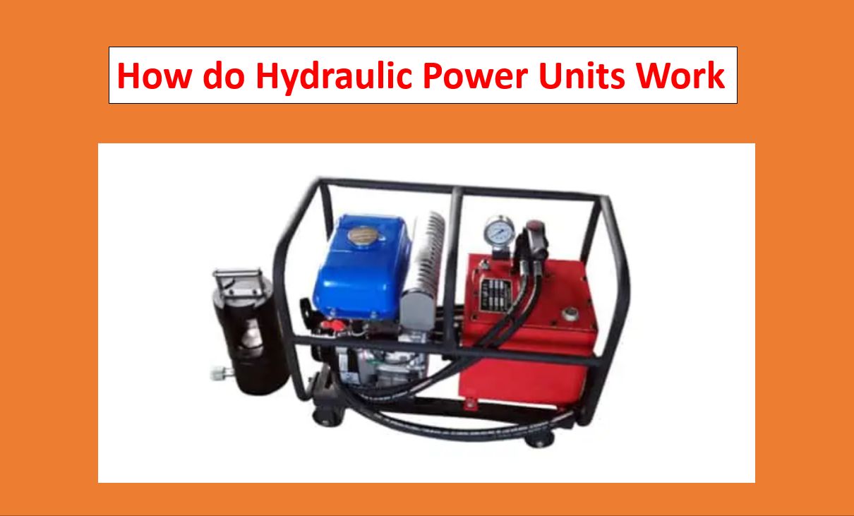
A hydraulic power unit, also known as a hydraulic systems pack, is an independent device typically consisting of a motor, fluid storage, and a pump. It operates by applying the hydraulic pressure required to power motors, cylinders, and other auxiliary components of a specific hydraulic system.
What Is the Process of a Hydraulic Power Pack?
An enclosed fluid is used in a hydraulic system to transport work from one origin to another, producing rotating motion, constant acceleration, or force. The power unit or pack provides the power required for this fluid transmission.
In contrast to conventional pumps, Hydraulic Power Pack Units transfer fluid using multi-stage pressurization networks and frequently include temperature control components. The types of projects for which a hydraulic systems unit can be used are determined by its mechanical attributes and requirements.
The performance of a hydraulic power generator is significantly influenced by several essential variables, including pressure restrictions, energy capacity, the reservoir volume. The physical parameters of the device, such as its size, power source, and pumping capacity, are also important factors. It may be good to look at the fundamental parts of a standard model used during industrial hydraulic systems to understand better the basic concepts and design elements of a hydraulic power unit.
Design elements for hydraulic power packs or units
The design of a large, robust hydraulic power unit will differ significantly from that of a standard pumping system in several ways. It will be made to operate in a variety of environmental situations. Among the common design elements are:
Accumulators: These are canisters that the hydraulic actuators can attach to. They are designed to produce and maintain hydraulic velocity in addition to the motor pipe system by collecting water from the circulating mechanism.
Engine Pumps: A hydraulic systems unit may contain a single motor pumping or several components, each with an accumulator valve. In a system with many pumps, typically, only one is active at once.
Tanks: A tank is a canister having a volume large enough to accommodate the drainage of liquid from pipes into it. Similarly, it may be necessary to drain actuator fluid into a tank.
Filters: Usually, a filter is mounted along the tank’s top. It is an independent bypass unit with a built-in motor, pump, and filter system. It can be used to open a multi-directional valve, which could be used to fill or empty the tank. Filters can frequently be replaced, whereas the power unit runs because they are self-contained.
Heaters and Coolers: An air conditioner can be put close to or behind the filter unit as part of the climate regulating procedure to keep temperatures from exceeding acceptable levels. In the same way, temperatures can be raised as necessary by using heating, such as a petroleum heater.
Power unit regulators: The operator interface, which includes smart switches, displays, and other monitoring features, is the hydraulic controller unit. It is typically found hooked into the power unit and is required to install and integrate a power source into a hydraulic system.
Advice on Choosing Hydraulic Power Motors
The motor, which is often chosen based on its velocity, torque level, and available power, is the power source, or guiding force, associated with most hydraulic power units. Long-term cost-efficiency can be increased and energy waste reduced by using a motor whose capacity and capabilities are compatible with the hydraulic systems unit.
Depending on the power source being used, different motor selection criteria apply. For instance, diesel or gasoline-powered motor has a somewhat even torque-to-speed curve and delivers a relatively constant amount of torque for both high and low operating speeds. In contrast, an electric engine has an initial torque significantly greater than its working torque. Therefore, if the internal combustion engine is not adequately linked with the hydraulic systems unit, it may be able to start a loaded pump but not supply enough power to get it up to operating speed.
Engine Size
Generally, a diesel or gas vehicle using a hydraulic systems unit must have a power rating at least twice as high as an electric motor appropriate for the same equipment. Finding a team that is the right size and won’t waste energy is crucial since the value of the electricity an electric motor uses throughout its working life typically exceeds the cost of the unit itself. The following factors can be used to determine the motor size if the pumping power and fluid level are both constant:
- Equine power
- Liters per second
- Psi, or pounds per square inch, pressure (psi)
- Efficiency of mechanical pumping
Because horsepower can be computed as the name signifies square (RMS), a smaller motor may be adequate for the project when the hydraulic ram may need varying pressure levels at different phases of the pumping process. The engine must, nonetheless, be able to deliver the necessary torque for the cycle’s greatest pressure level. Once the arms and torques (including the beginning and operational and strategic levels) have been determined, they can be compared to the performance tables of a motor manufacturer to evaluate whether the motors are the right size.
Hydraulic power units’ operational procedures
The gear pump moves hydraulic fluid from the tank into an accumulator as soon as a hydro-power unit starts working. This procedure continues until a charging valve enables the pumping motion to start fluid circulation when the pressure inside the accumulation reaches a specific level. As a result, the pump releases fluid at low pressure through a charge valve and back into the tank. The accumulator is sealed off from fluid flow by a specific one-way valve. Still, if the volume lowers significantly, the charging nozzle reactivates, and the battery is refilled using fluid. A reduced-pressure valve further along the line controls how much oil is sent to the actuators.
To enable other accumulators to charge pressures as well, if an accumulator has a fast-stroking device, this can be linked to other accumulators. Frequently, a fan or automatic thermostat will be added to help lower rising temperatures. A temp switch can turn off the motor pump and aid in replenishing the tank if the fluid levels get too low if the system fluid starts to overheat. A flow switch might cause the hydraulic power unit’s numerous motor pumps to alternate if there is a decreased fluid supply. Monitoring can notify operators when accumulator pressure has fallen too low, increasing the danger of a power unit failure. Pressure switches could be used to control accumulator pressure.
See also – Sugar Daddy and Sugar Baby